Assignment:
In week no. 4 we are required to do an in circuit programmer by milling the Printed Circuit Board “PCB” machine using “David” board downloaded from the link.
Eagle:
I started downloading the eagle auto-desk software from http://www.auae todesk.com/products/eagle/free-download so that we can pull the David Board for having the required schematic to mill it.
David board Schematic
After having the board opened in eagle I converted it to Gerber file by cam processor so the the Cirqwizard in which the milling machine “Cirqouid” can read the file.
PCB
The milling machine used for our assignment is the Cirqouid in which Cirqwizard is the software used for reading the board file and do all the necessary configuration before milling.
We are using a copper board for the milling due to is conductivity and the perfect material to for combining it with electronic materials and a extra copper clad for precaution not to break the bits.
Inserting the copper in the Cirqouid
I inserted the 0.2 mm bit for tracing the schematic uploaded from Eagle to Cirqwizard. Cirqouid have three Axis as in path x,y and z (depth). For tracing, first wee needed to insure the right depth and coordinate are set for drawing the board thus by trial and error once we found the right Axis for tracing we started the milling.
After finishing the schematic tracing, I Insert the 2 mm bit to cut the copper board and making holes on each side so that the board will not get tilted.
Steps in Cirqwizard for setting the schematic to mill the Cirqouid (PCB):
AtPanelUploading the “David” board from eagle to Cirqwizard
In Offset he 0.2mm bit inserted, in this setup you move the x,y
and z -axis and you do the trial and error for the depth (z-axis)
Problem:
One main issue is that the depth z-axis is that I went to to deep in the trial and error that I needed to change my x & y axis to start again.
The 0.2mm is tracing the schematic in the PCB After finishing you chane to 2.0.mm to start cutting
The holes of the sides that will cut the copper board Once pressing the continue the bi will start cuuting
Note: we continued cutting through 2.0 mm
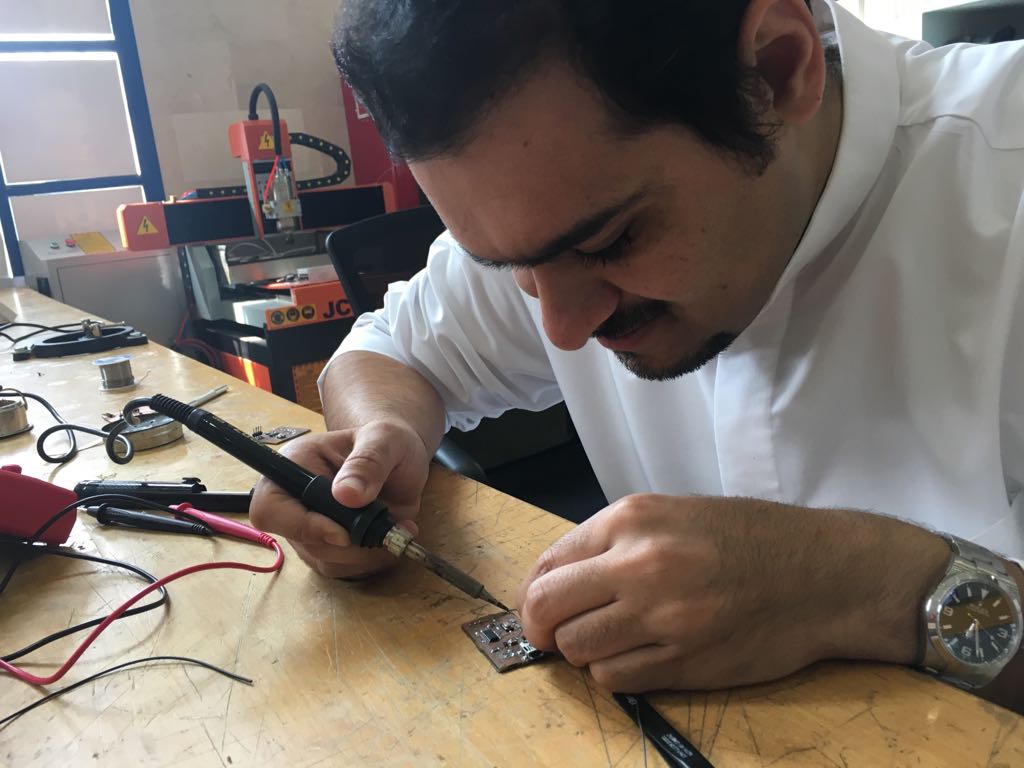
Soldering:
After the the board is compleed the next step it to add the componets as it shows in the David Board.
Components Used:
1- attiny 44
2- resistor 1 k, 499, 2 49, 10k and 0 ohm
3- capacitor 0.1 & 10 uf, 2 18 pf
4- Resonater 12 mhz
5- 2 solder jumper
6- Zener Diode 2 3.3 V
Result:
The compnents are installed in the copper board and prepared for programming
Programming
After finalizing the board with all required components, I have started the programing process of the board.
I opened the terminal to install the software. beofore installing i used the following codes
1 -first , I typed [sudo apt-get install flex byacc bison gcc libusb-dev avrdude]
2 -then I typed [sudo apt-get install gcc-avr] (typing Y when asked to do so )
3 -then [sudo apt-get install avr-libc]
4 -finally, i typed [sudo apt-get install libc6-dev]
I started my ISP program through the following steps:
1- we make clean
2- we make hex
3- we make fuse
4- we make program
Finally, the program is insalled.
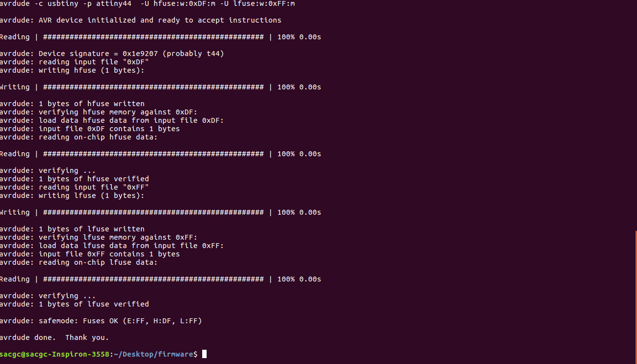
The pic shows I am inserting the programming in the "Terminal".
After programming I removed the solder jumper.